9k 93 95 NG900 Box Build -Faero Style! Finished....
Posted: Wed Oct 05, 2011 2:09 pm
I was going to wait until i got it all together but I'll just go with the step by step post method so any trouble can be caught on the fly. Aim is to consolidate it all at the end into a useful document...
In this case the build is for a 9k box with quaife LSD but the build is identical for 9-3 and GM900 internally. Photos with the iPhone so apols for the quality but they give you the message.
The groundwork was done here: This includes parts, prices etc etc.
REFERENCE: http://www.uksaabs.co.uk/UKS/viewtopic.php?f=32&t=74303
The Quaife was done here - Mark D's thread with some bits on the end from me.
QUAIFE http://www.uksaabs.co.uk/UKS/viewtopic.php?f=2&t=81411&hilit=quaife
IMPROVEMENTS / REFRESHES
This is an area that could go on forever so it was a case of cherry picking the cost effective ones and we'll see how it works out.
1) START WITH A DECENT BOX! This is hard these days but if you have one that's at least not been in a tuned car there is hope. You can also drive a 2litre injection like an idiot and wreck the box. This is the gamble but take your time to find the donor(s).
2) PLAN YOUR RATIOS: Final Drive choice: 3.61, 3.82, 4.05, 4.45. 3rd gear: 1.12 or 1.18. 5th gear : 0.7 or 0.66.
From that lot you can really play about. The smaller the number, the taller the gear. For my plan I'm going with 4.45 + 1.12 3rd, and 0.66 5th. One theory says that "the shorter the FINAL drive, the less relative stress there is on the internal gears"
3) FRESHEN UP: I'm doing the entire bearing set including needles - All Timken (non-Saab source). See Knowledgebase thread above.
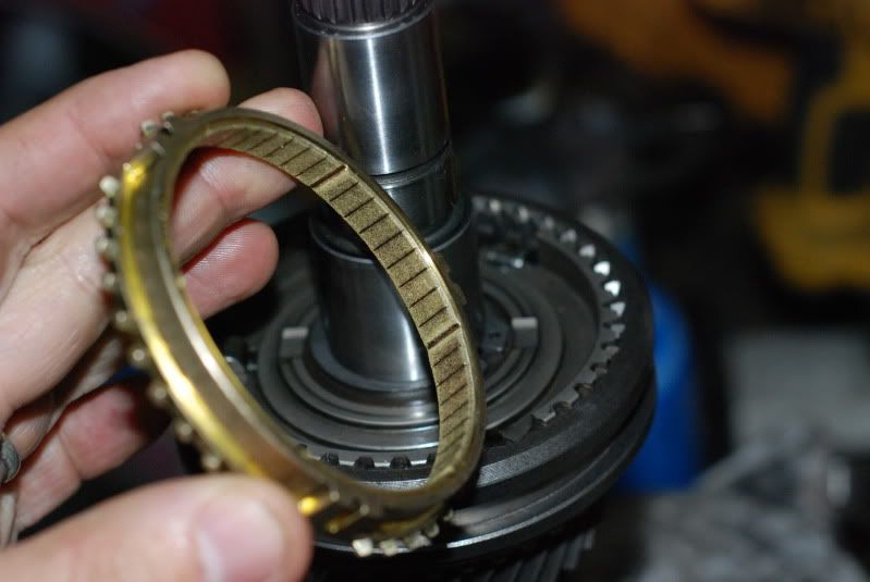
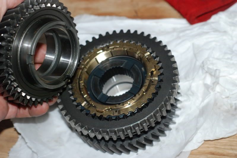
New syncros: 2nd, 3rd, 4th, 5th. I got them cheap so suggest this would not be cost effective normally.
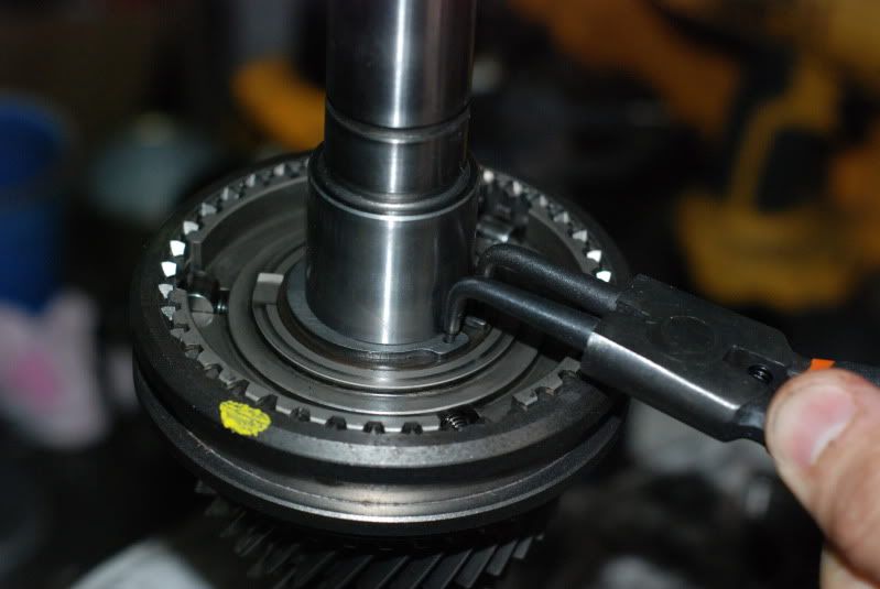
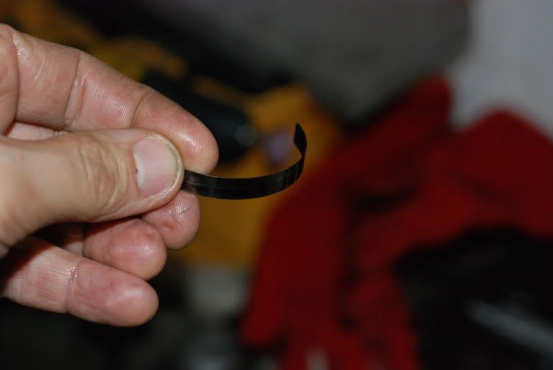
New Circlips: 3rd, 4th, 5th on input shaft.
4) MODIFY:
GEAR TOUGHENING: 2nd, 3rd, 4th pairs are all Shot Peened and Cryo Treated. This means the input shaft is done as 2nd gear input is part of the shaft itself. The first batch were also superfinished (posh!) but the entire sets were trashed by the courier in spectacular fashion. Not as expensive as you'd think. This idea will not work if the gears already have big internal cracks but once again , that's the gamble.
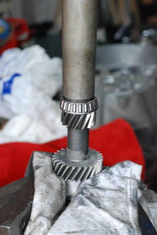
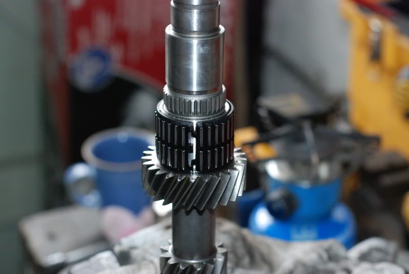
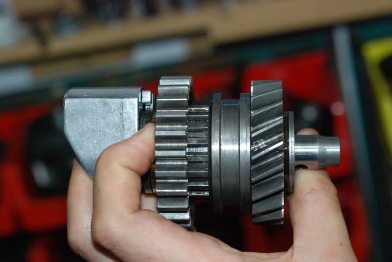
INPUT SHAFT:
Mod shaft to run the later 3rd gear circlip and syncro hub. £20 at local machine shop. Hubs from any 9-3 or very late 9ks/GM900s. See Reference link above.
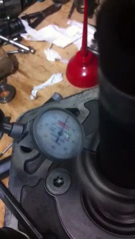
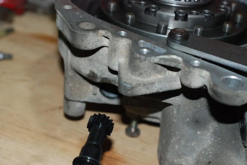
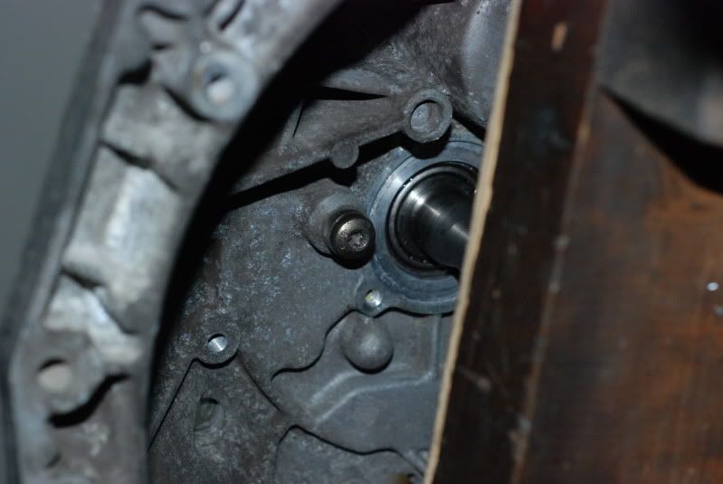
OUTPUT SHAFT SUPPORT: Dowel location mod. This was Nick T's one after seeing movement around the bolt but has been tweaked and made easier for those without a milling machine by Mark D. This would make it the 'Degiorgio Dowell' ...
See below
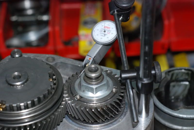
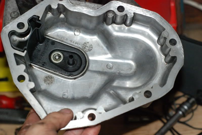
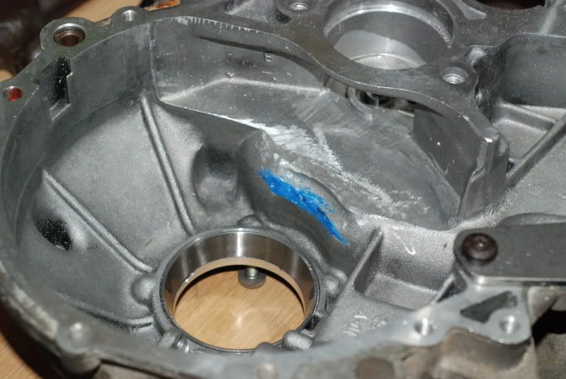
OUTPUT SHAFT BEARING SHELL LOCATION: The pinion bearing shell can spin once loaded up - it works loose in the casing and creates a groove in the back of the bearing support plate. This will be loctited into position. Thanks to Mark D for spotting and Nick T for confirming fix for this one.
See below
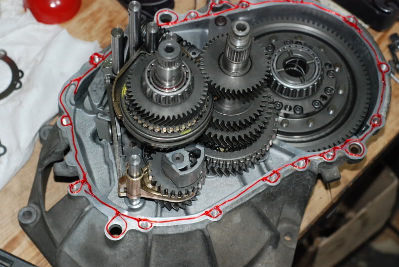
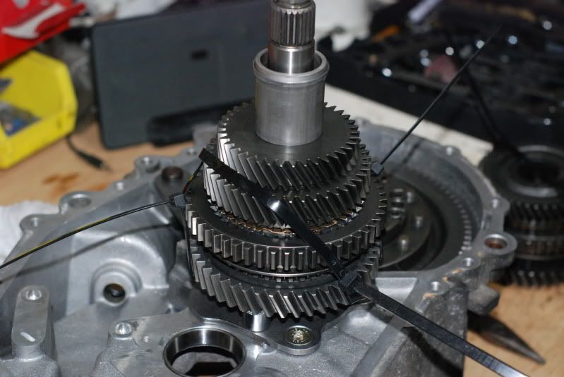
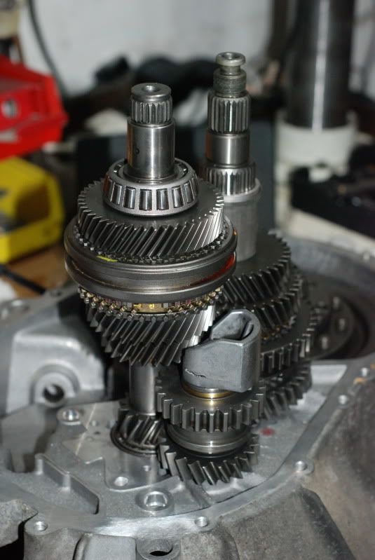
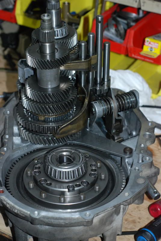
THE BUILD
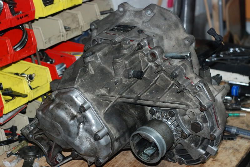
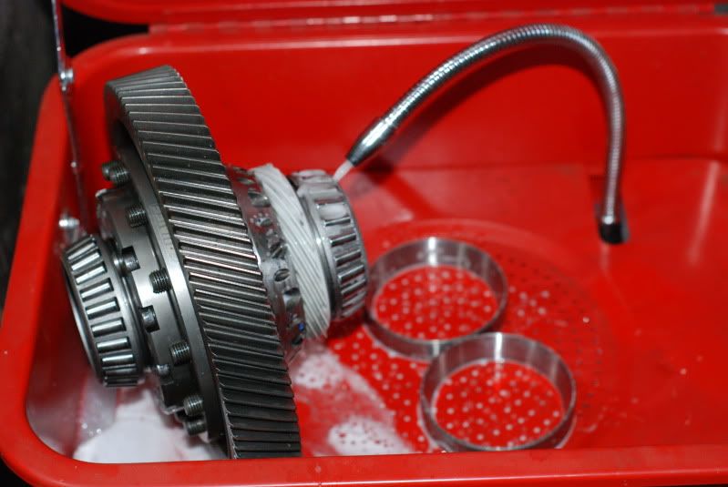
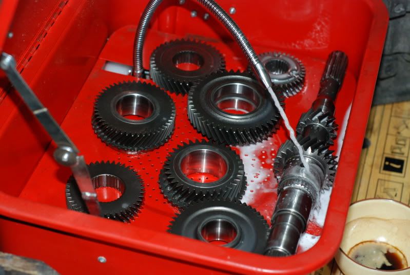
STEP 1 : CLEAN THE CASING
I washed mine down in petrol and then jet washed it for about 20mins until it looked a bit shinier.
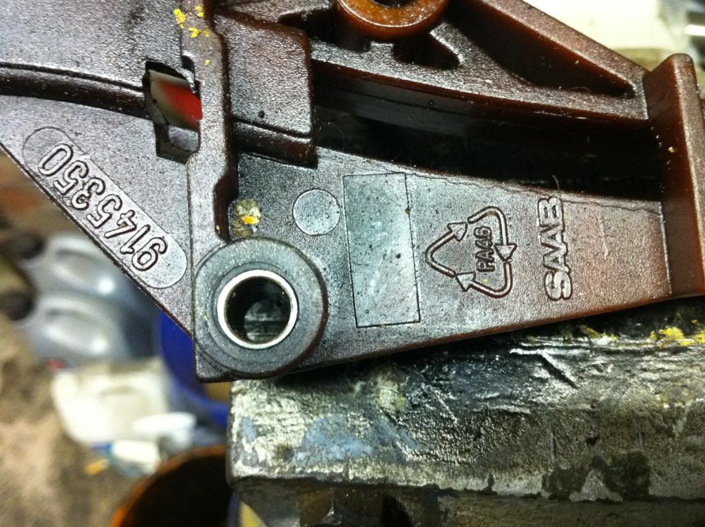
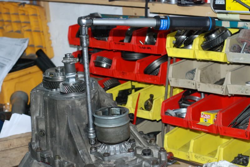
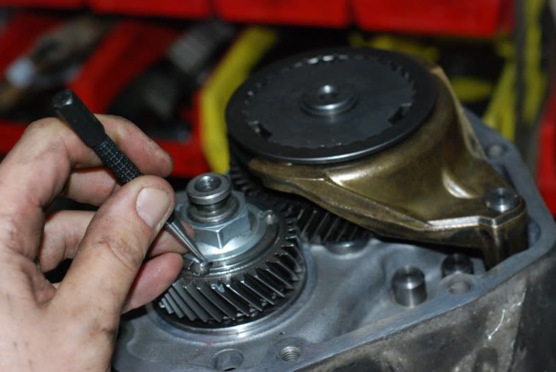
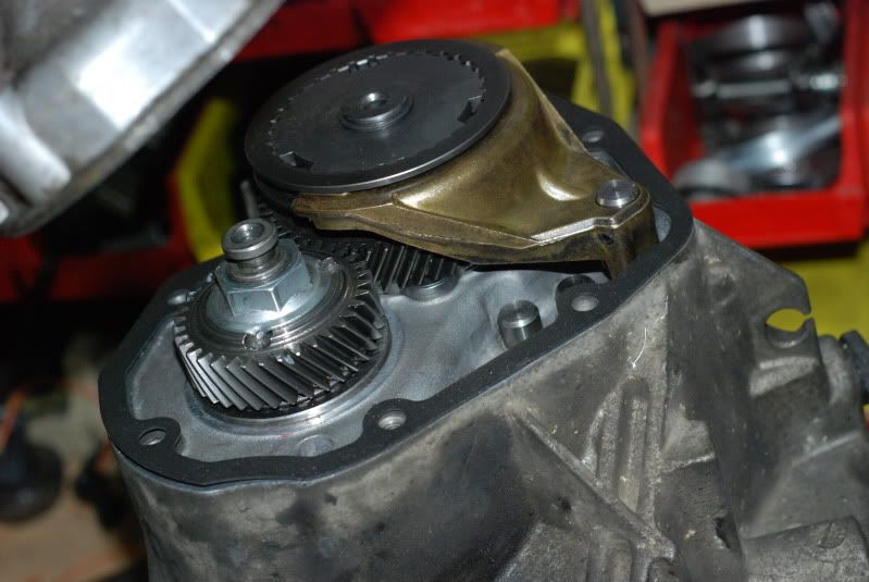
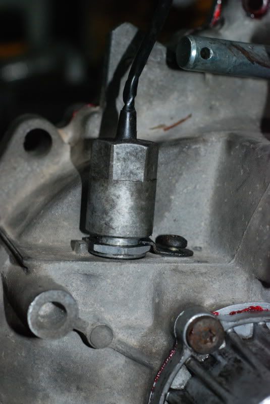
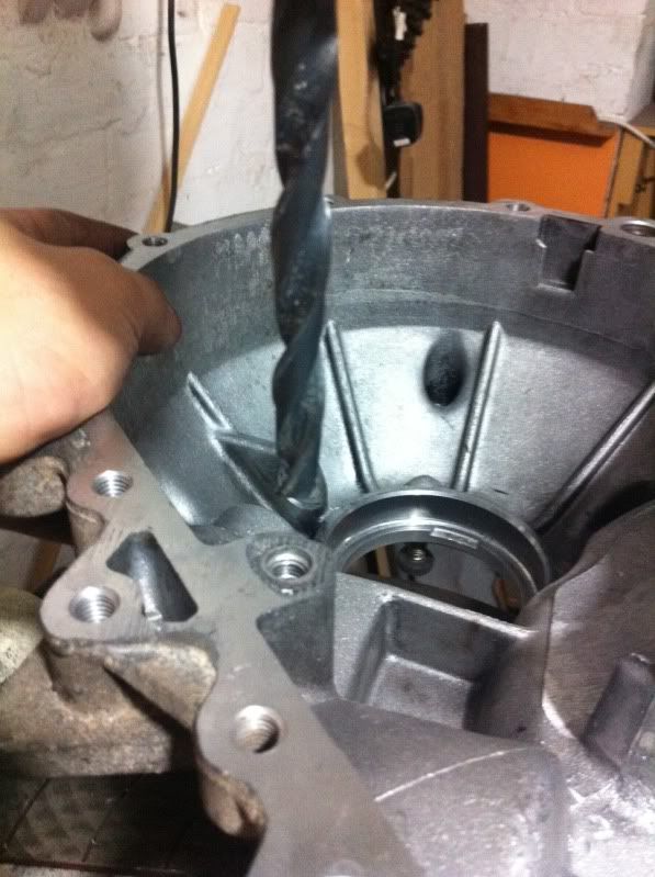
STEP 2: The DOWELL MOD:
The standard design has a lot of slop so the casing can twist a little under heavy load. We don't want this.
Required:
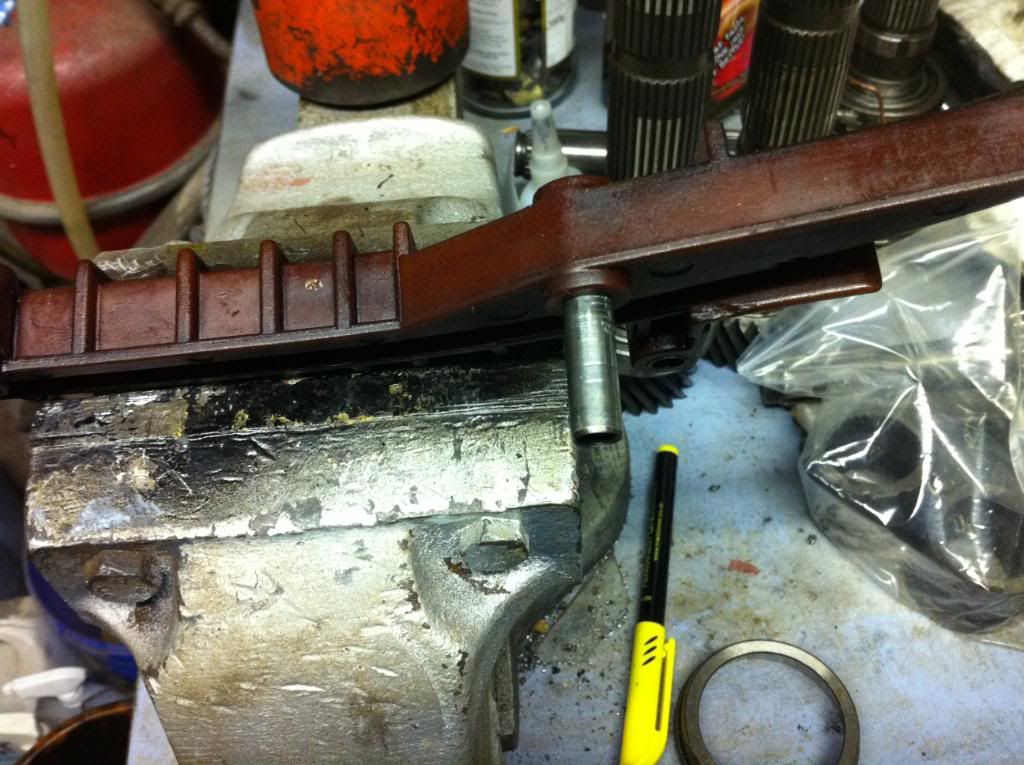
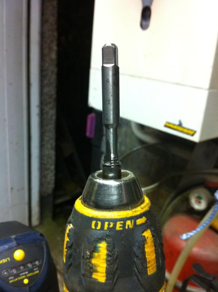
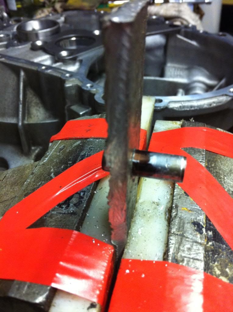
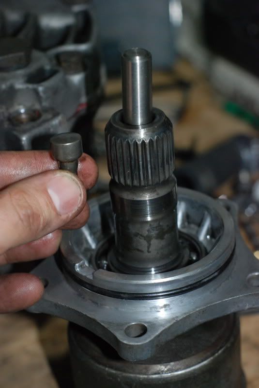
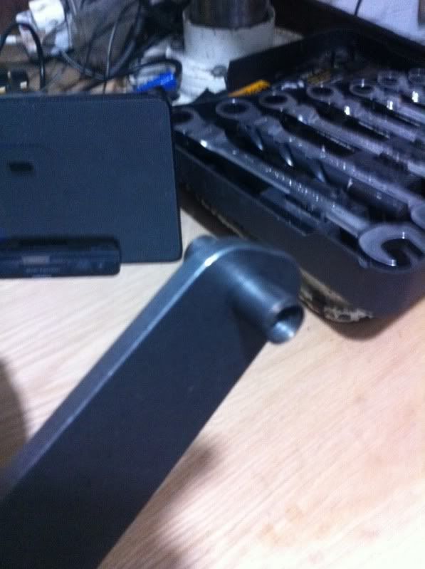
Dowell from balance chain mech. Tap to M8 thread internal.
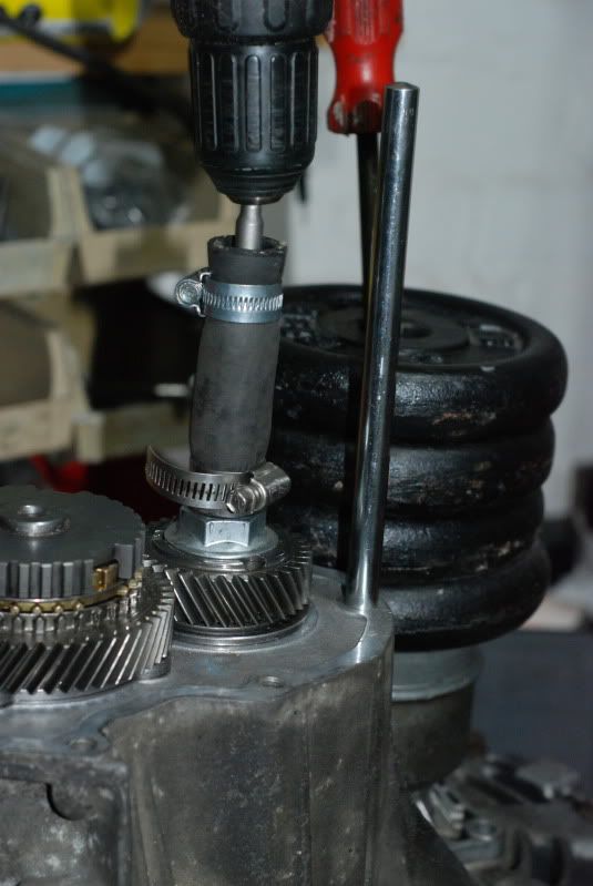
Sharp 9mm drill bit + big pillar drill if you have it.
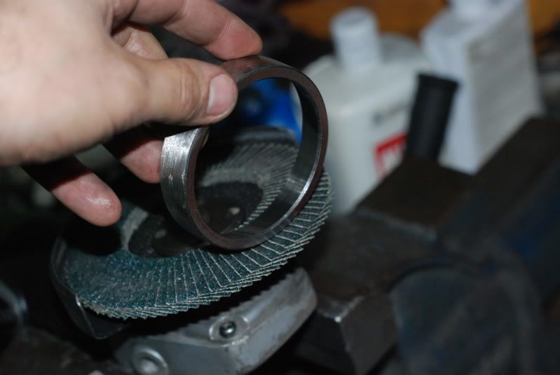
Grinder with 1mm slice disc.
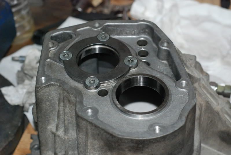
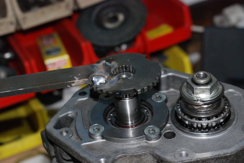
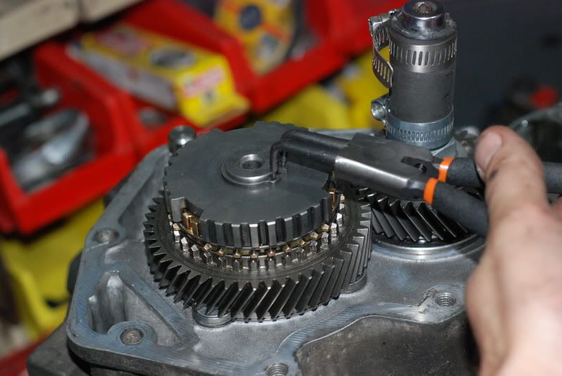
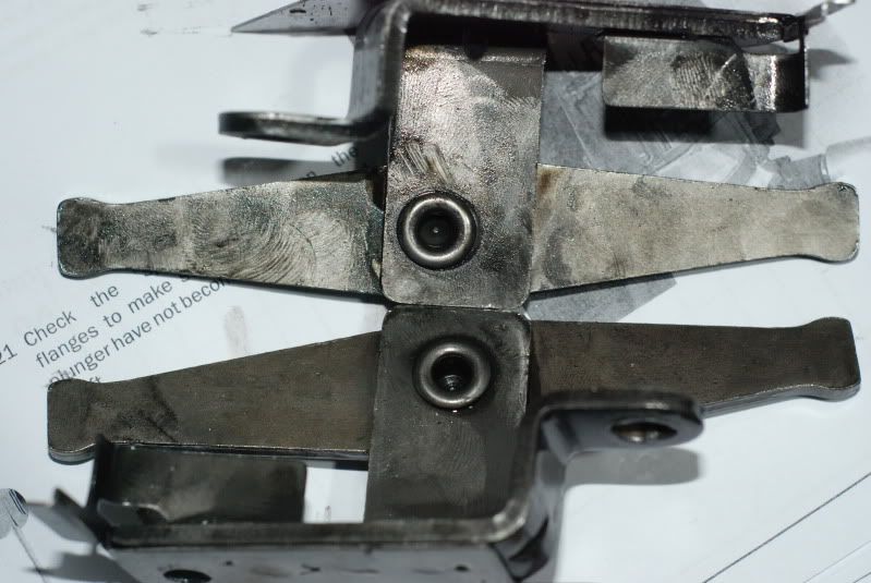
Check that the bearing support plate is not damaged from previous exploits with loose bearing shells. (i.e. the underside of the round part of the plate is smooth with no ridge from wear)
Clear the hole in the plate to 9mm. Just enough for friction fit of the dowel
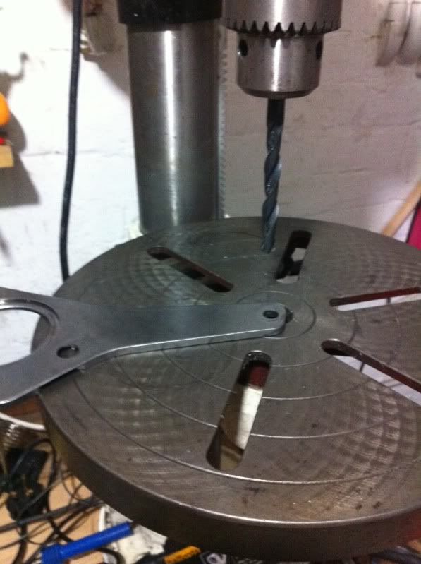
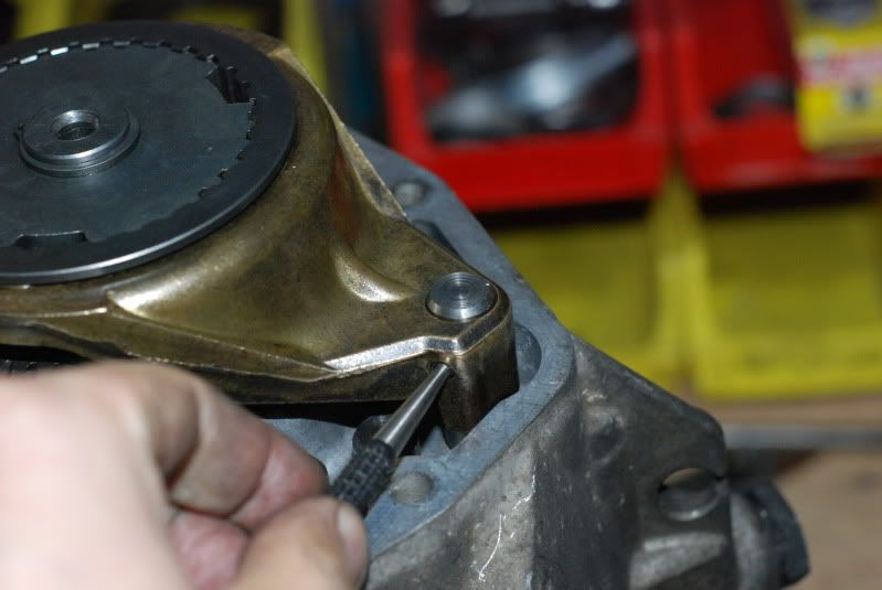
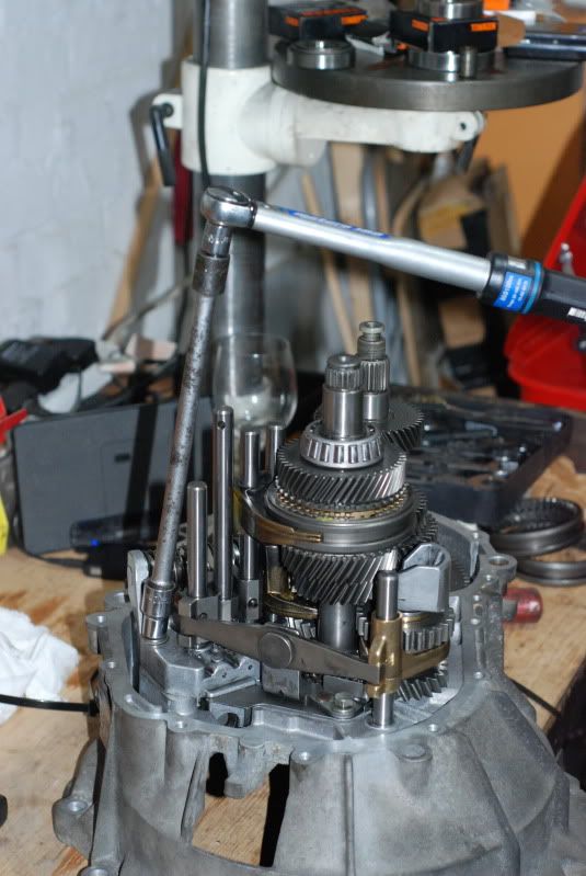
Take the casing and get it really flat - line up the 9mm drill and take the hole down to approx 5mm max from the surface.
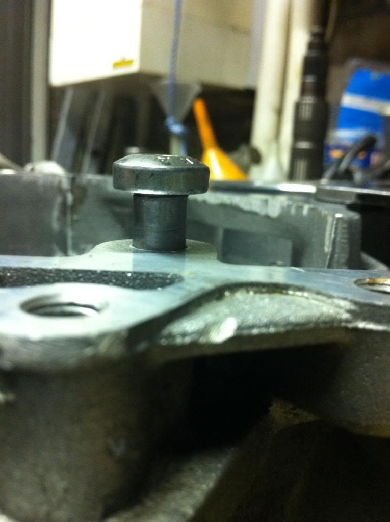
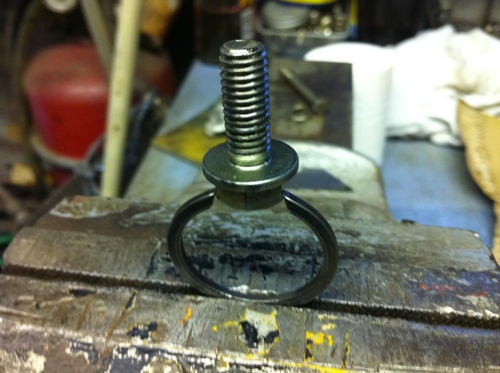
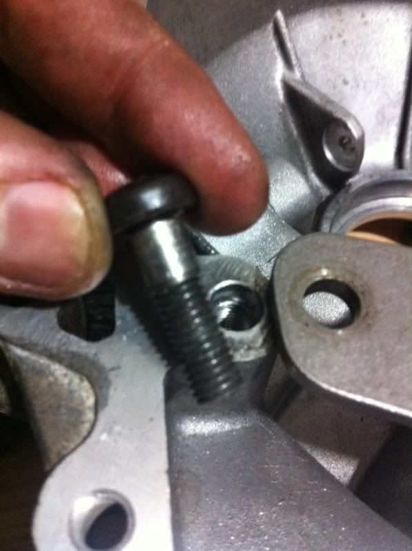
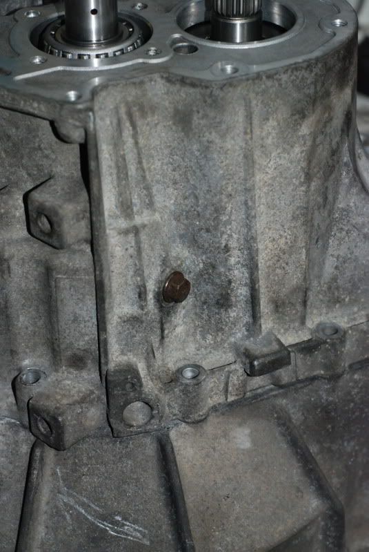
Ditch the original torx bolt and use a Cam cover bolt. Cut it to about 5mm longer than the original bolt. This makes up for some of the lost thread caused by the Dowell.
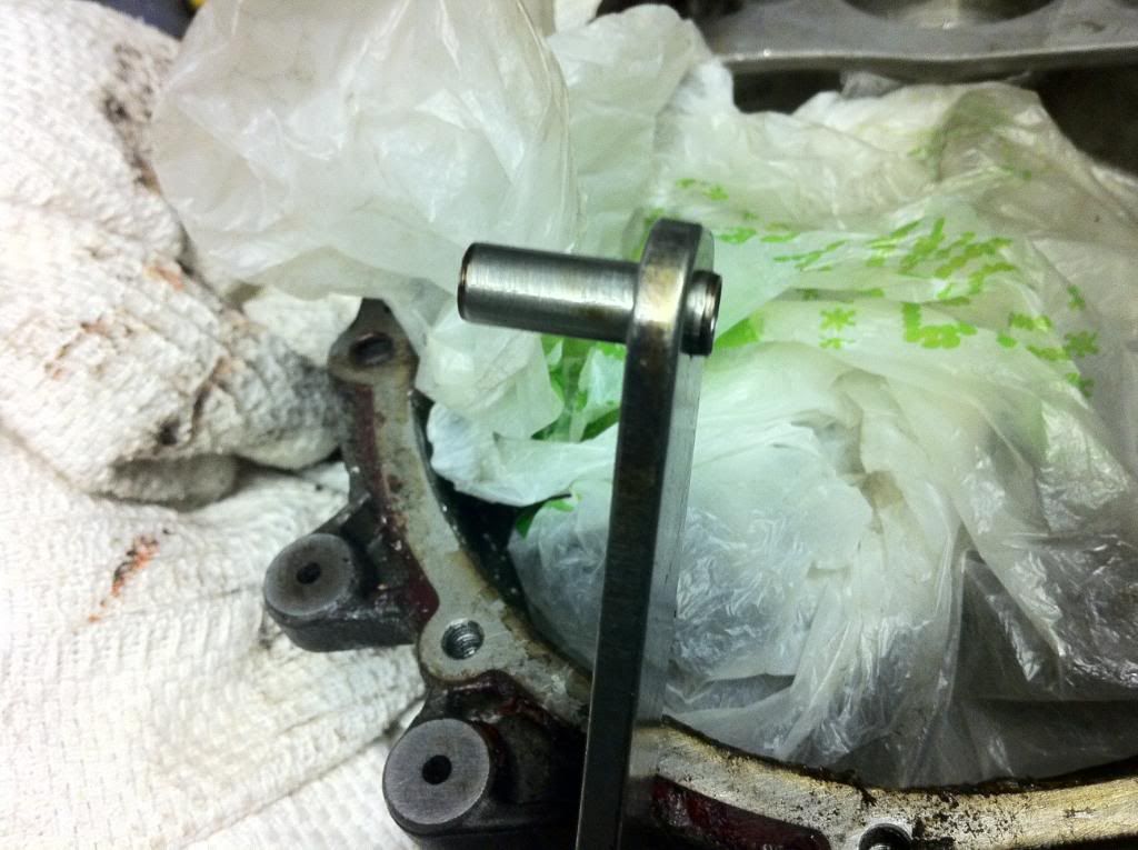
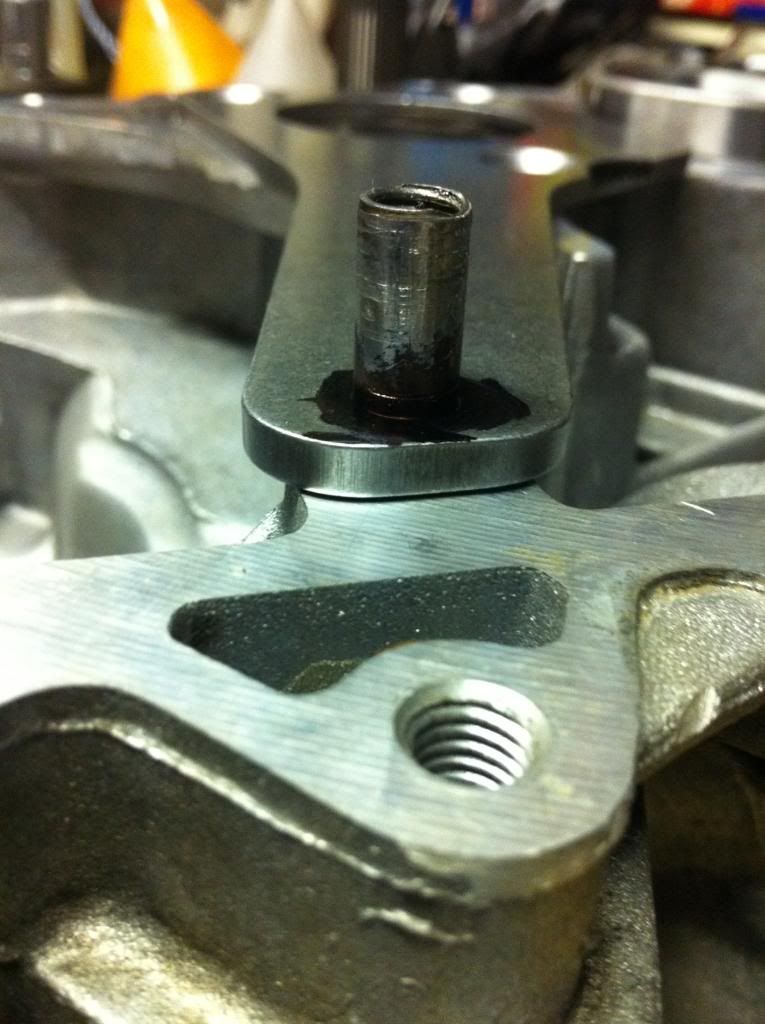
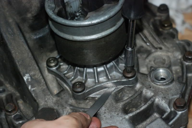
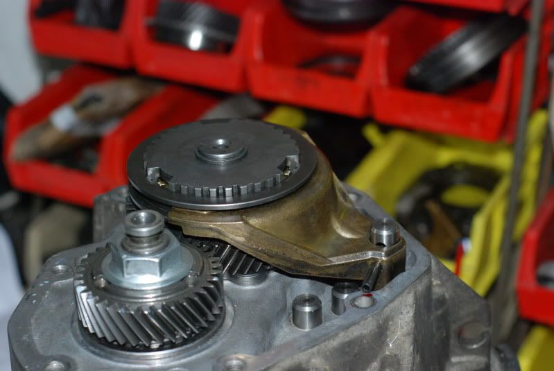
Carefully sit the dowell into a position where the top of the dowell is just below the top of the bearing plate. We want to make sure the head of the bolt still clamps on the plate. Take account that the dowell will not go right to the top of the bolt.
Run the dowell as far up the bolt as you can and test fit. Check the 3 chamfered bolt holes around the bearing all line up ok too.
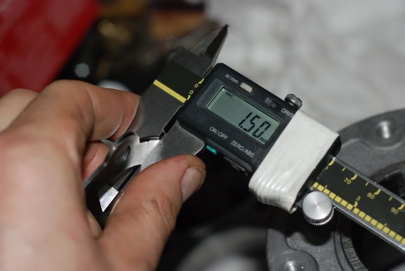
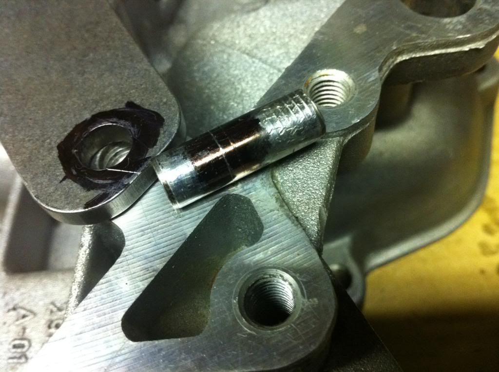
The Dowell will be just under 10mm long. 5mm in the casing and 4.5mm in the bearing plate.
So - you now have zero slop in the main box strengthening plate.... in theory!
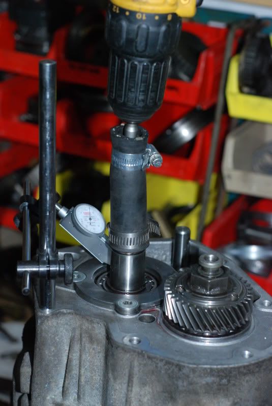
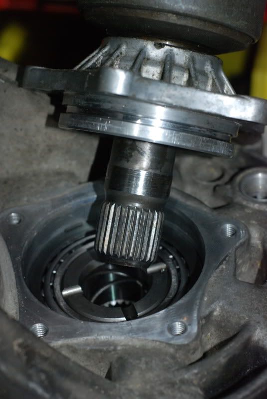
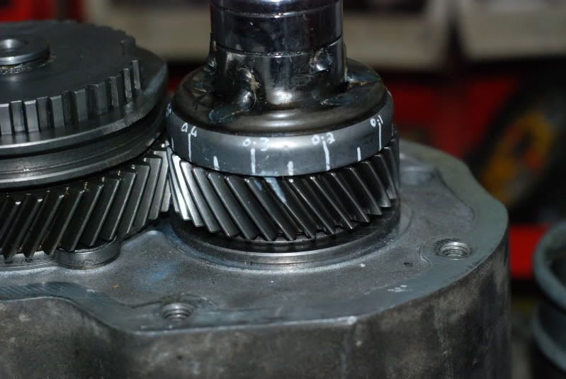
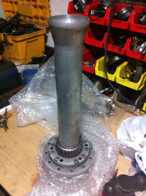
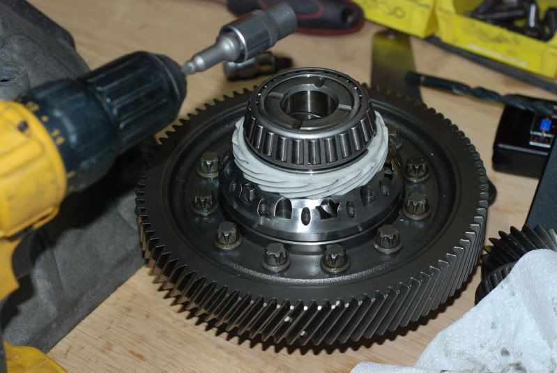
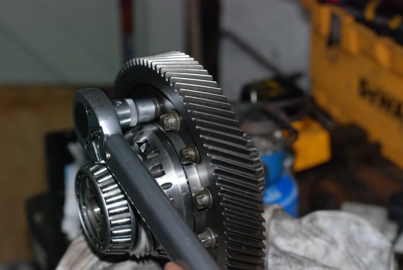
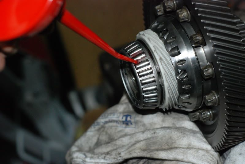
STEP 3 FITTING THE DIFF BEARINGS:
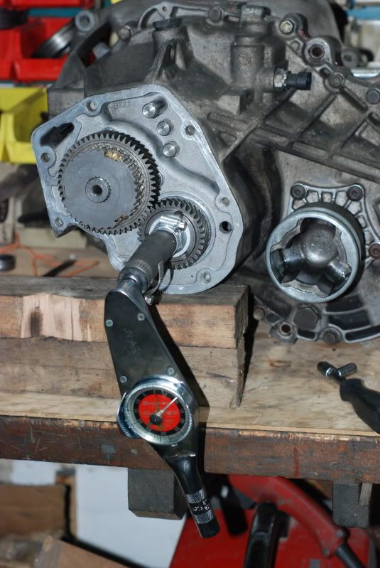
This is the first step to preparing the diff. I don't have many special tools so will use heat/cool method where-ever I can to help me along.
1) Chill the diff in the freezer. I did it overnight. It can be disguised as a small chicken if this is deemed unacceptable by the freezers owner...
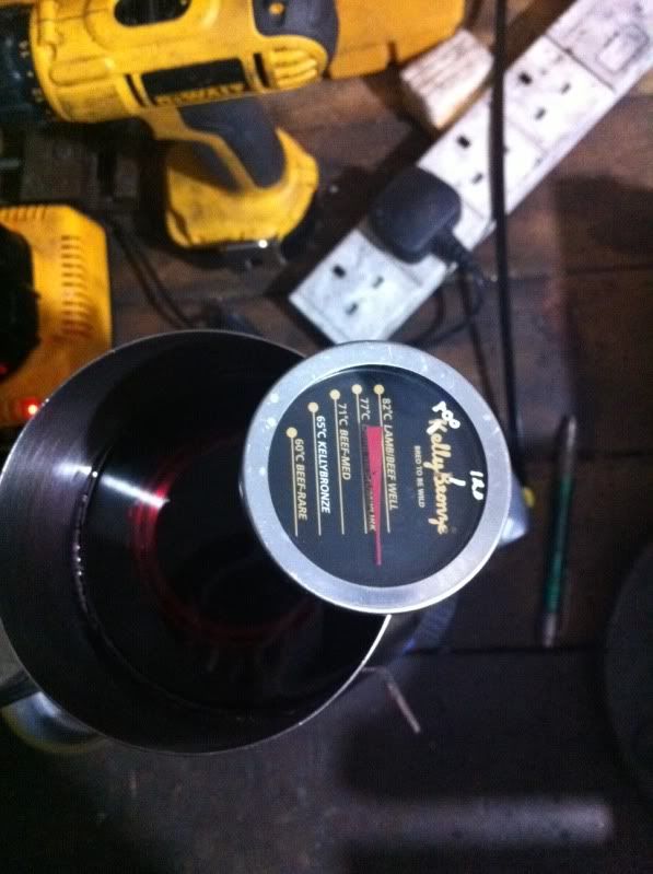
2) Heat the bearings in a tin to about 120C - No higher as apparently damage can be caused.
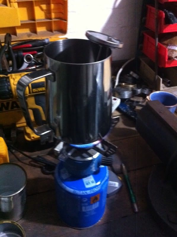
As you can see I use a Kelly Bronze Turkey thermometer for something much more useful...
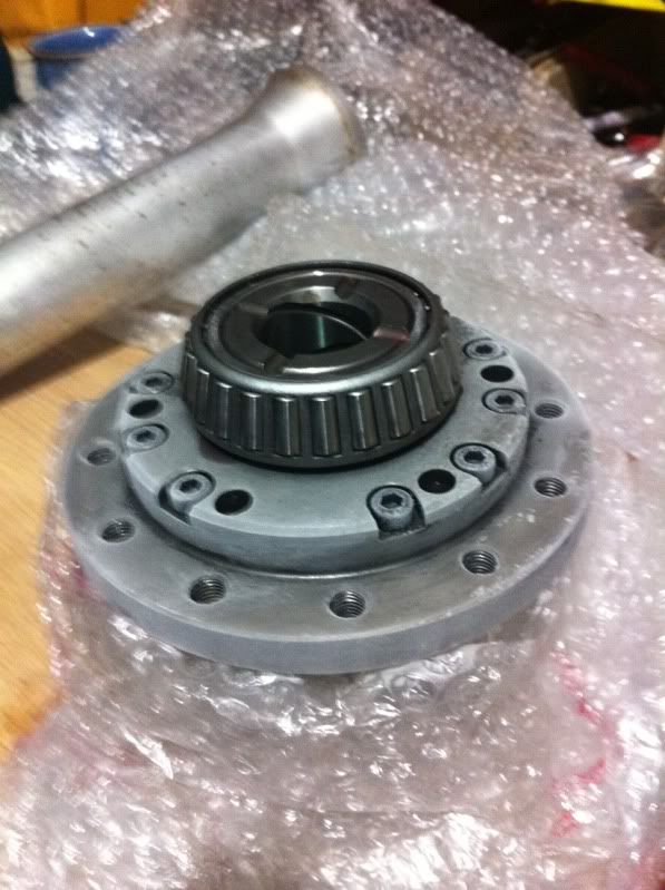
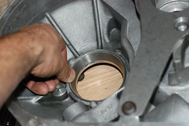
3) You will find that the aluminium intermediate driveshaft cover is a perfect match for the bearing centre - In this case it's for backup as it really is not needed.
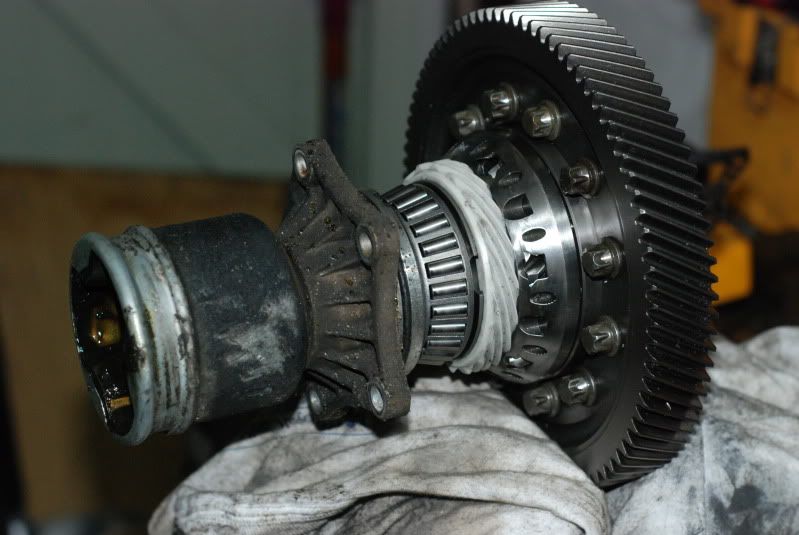
4) Lift out the bearings with pliers and using gloves, drop them onto the diff. Literally - they will FALL into position.
Quick tap if you must:
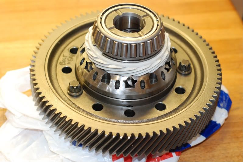
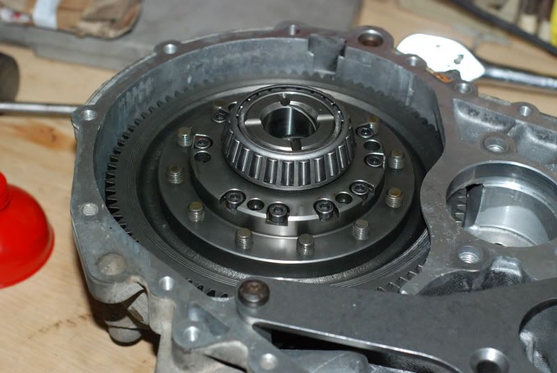
5) All done! A relaxing start to this job tbh. The will undoubtedly be trouble ahead!
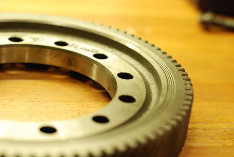
NEXT EXCITING INSTALLMENT WILL FIT THE CROWNWHEEL TO THE DIFF
In this case the build is for a 9k box with quaife LSD but the build is identical for 9-3 and GM900 internally. Photos with the iPhone so apols for the quality but they give you the message.
The groundwork was done here: This includes parts, prices etc etc.
REFERENCE: http://www.uksaabs.co.uk/UKS/viewtopic.php?f=32&t=74303
The Quaife was done here - Mark D's thread with some bits on the end from me.
QUAIFE http://www.uksaabs.co.uk/UKS/viewtopic.php?f=2&t=81411&hilit=quaife
IMPROVEMENTS / REFRESHES
This is an area that could go on forever so it was a case of cherry picking the cost effective ones and we'll see how it works out.
1) START WITH A DECENT BOX! This is hard these days but if you have one that's at least not been in a tuned car there is hope. You can also drive a 2litre injection like an idiot and wreck the box. This is the gamble but take your time to find the donor(s).
2) PLAN YOUR RATIOS: Final Drive choice: 3.61, 3.82, 4.05, 4.45. 3rd gear: 1.12 or 1.18. 5th gear : 0.7 or 0.66.
From that lot you can really play about. The smaller the number, the taller the gear. For my plan I'm going with 4.45 + 1.12 3rd, and 0.66 5th. One theory says that "the shorter the FINAL drive, the less relative stress there is on the internal gears"
3) FRESHEN UP: I'm doing the entire bearing set including needles - All Timken (non-Saab source). See Knowledgebase thread above.
New syncros: 2nd, 3rd, 4th, 5th. I got them cheap so suggest this would not be cost effective normally.
New Circlips: 3rd, 4th, 5th on input shaft.
4) MODIFY:
GEAR TOUGHENING: 2nd, 3rd, 4th pairs are all Shot Peened and Cryo Treated. This means the input shaft is done as 2nd gear input is part of the shaft itself. The first batch were also superfinished (posh!) but the entire sets were trashed by the courier in spectacular fashion. Not as expensive as you'd think. This idea will not work if the gears already have big internal cracks but once again , that's the gamble.
INPUT SHAFT:
Mod shaft to run the later 3rd gear circlip and syncro hub. £20 at local machine shop. Hubs from any 9-3 or very late 9ks/GM900s. See Reference link above.
OUTPUT SHAFT SUPPORT: Dowel location mod. This was Nick T's one after seeing movement around the bolt but has been tweaked and made easier for those without a milling machine by Mark D. This would make it the 'Degiorgio Dowell' ...
See below
OUTPUT SHAFT BEARING SHELL LOCATION: The pinion bearing shell can spin once loaded up - it works loose in the casing and creates a groove in the back of the bearing support plate. This will be loctited into position. Thanks to Mark D for spotting and Nick T for confirming fix for this one.
See below
THE BUILD
STEP 1 : CLEAN THE CASING
I washed mine down in petrol and then jet washed it for about 20mins until it looked a bit shinier.
STEP 2: The DOWELL MOD:
The standard design has a lot of slop so the casing can twist a little under heavy load. We don't want this.
Required:
Dowell from balance chain mech. Tap to M8 thread internal.
Sharp 9mm drill bit + big pillar drill if you have it.
Grinder with 1mm slice disc.
Check that the bearing support plate is not damaged from previous exploits with loose bearing shells. (i.e. the underside of the round part of the plate is smooth with no ridge from wear)
Clear the hole in the plate to 9mm. Just enough for friction fit of the dowel
Take the casing and get it really flat - line up the 9mm drill and take the hole down to approx 5mm max from the surface.
Ditch the original torx bolt and use a Cam cover bolt. Cut it to about 5mm longer than the original bolt. This makes up for some of the lost thread caused by the Dowell.
Carefully sit the dowell into a position where the top of the dowell is just below the top of the bearing plate. We want to make sure the head of the bolt still clamps on the plate. Take account that the dowell will not go right to the top of the bolt.
Run the dowell as far up the bolt as you can and test fit. Check the 3 chamfered bolt holes around the bearing all line up ok too.
The Dowell will be just under 10mm long. 5mm in the casing and 4.5mm in the bearing plate.
So - you now have zero slop in the main box strengthening plate.... in theory!
STEP 3 FITTING THE DIFF BEARINGS:
This is the first step to preparing the diff. I don't have many special tools so will use heat/cool method where-ever I can to help me along.
1) Chill the diff in the freezer. I did it overnight. It can be disguised as a small chicken if this is deemed unacceptable by the freezers owner...
2) Heat the bearings in a tin to about 120C - No higher as apparently damage can be caused.
As you can see I use a Kelly Bronze Turkey thermometer for something much more useful...
3) You will find that the aluminium intermediate driveshaft cover is a perfect match for the bearing centre - In this case it's for backup as it really is not needed.
4) Lift out the bearings with pliers and using gloves, drop them onto the diff. Literally - they will FALL into position.
Quick tap if you must:
5) All done! A relaxing start to this job tbh. The will undoubtedly be trouble ahead!
NEXT EXCITING INSTALLMENT WILL FIT THE CROWNWHEEL TO THE DIFF
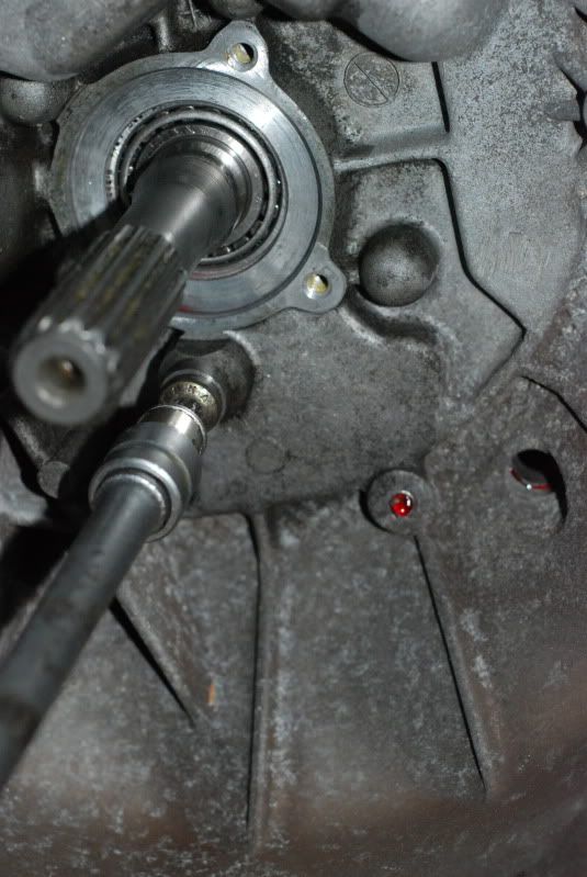
 .....is this good practice?